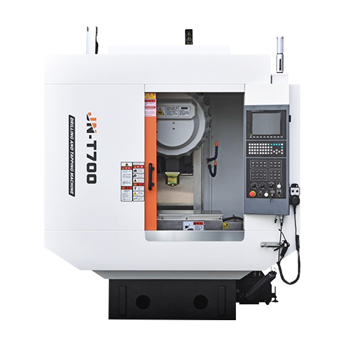
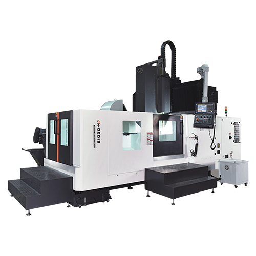
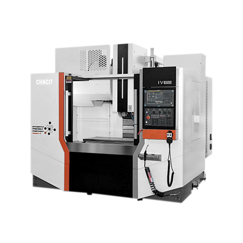
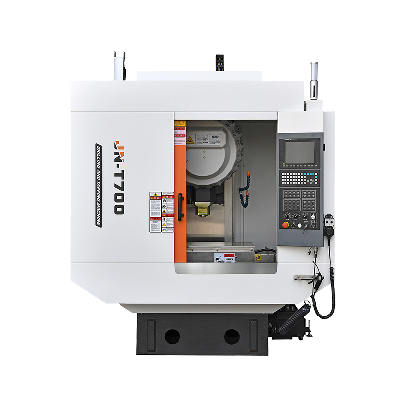
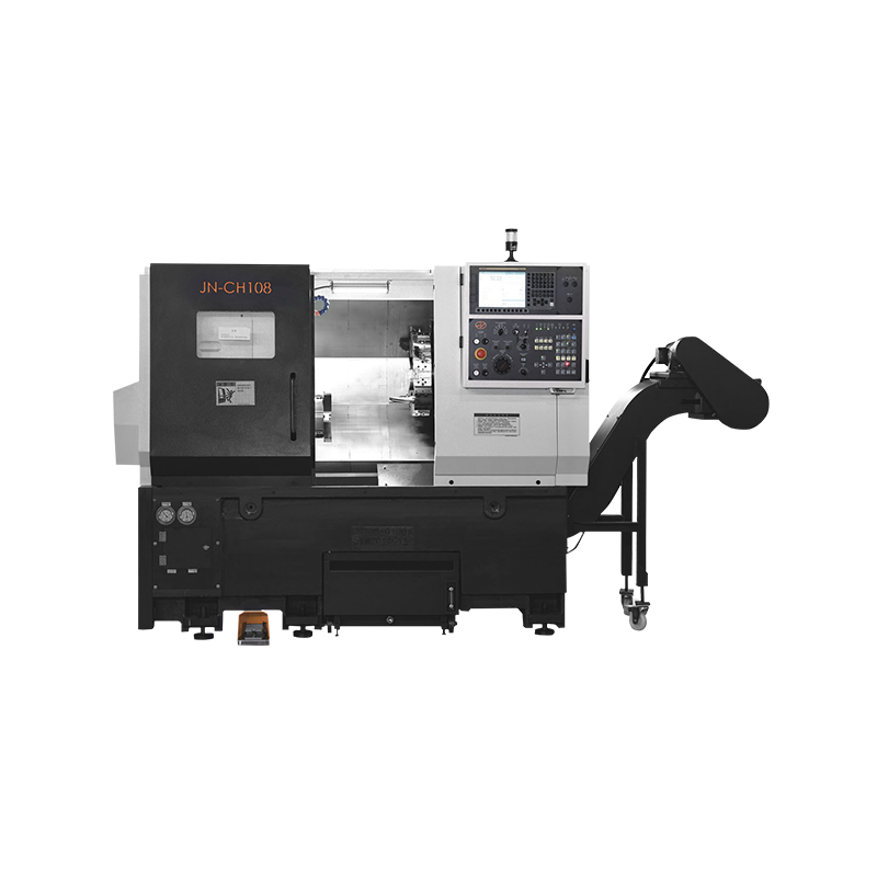
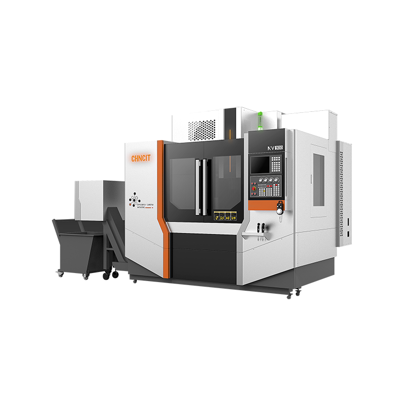
Machining flexibility for various operations like milling, drilling, and tapping;
High precision and efficiency;
Three system choices: Fanuc, mitsubishi, and siemens 828d, with standard original motors;
Belt or Direct type options available for specific product machining requirements.
VIEW MORE 
-
 WHATSAPP
 -
 INS
INS -
 WECHAT
Why Does CNC Mill Drill Vibrate
Author: CHNCIT
Date: May 08, 2026
Strange vibration marks on machined parts are one of the issues frequently discussed across machining forums, operator communities, and factory maintenance groups. Excessive vibration not only affects surface finish, but also shortens spindle life, damages cutting tools, and increases machining deviation during long production cycles.
Many buyers searching for a reliable CNC Mill Drill For Sale often focus only on spindle power or travel size, while machine rigidity and vibration control are equally important. A modern CNC Drilling Milling Machine must maintain stable cutting performance under different materials and continuous operation conditions.
Common Signs of CNC Mill Drill Vibration
Operators can usually identify vibration problems through visible and audible changes during machining.
Typical symptoms include:
- Ripple marks on machined surfaces
- Unstable drilling hole diameter
- Loud high-frequency cutting noise
- Premature tool wear
- Abnormal spindle temperature rise
- Poor dimensional repeatability
- Visible chatter marks during side milling
Reddit discussions and machining forums also mention sudden vibration appearing during corner cutting or deep-hole drilling. Some users report vibration only under specific spindle speeds or tool lengths.
Machine Rigidity Directly Affects Stability
A weak machine structure is one of the major causes of vibration.
Heavy cutting generates dynamic force between the cutting tool and workpiece. Machines with insufficient rigidity allow small movements between components, which gradually develop into chatter.
Several structural areas influence rigidity:
1. Machine Bed Design
A heavier cast-iron bed generally absorbs vibration more effectively than lightweight structures.
Many industrial CNC drilling and milling systems use:
- HT300 high-strength cast iron
- Rib-reinforced column structures
- Wide guideway support
- Integrated base casting
Some factory users underestimate the importance of machine weight. However, a stable machine base reduces resonance significantly during high-speed milling.
2. Spindle Assembly
Spindle imbalance is another major vibration source.
Common spindle-related problems include:
- Bearing wear
- Improper dynamic balancing
- Thermal expansion
- Loose taper contact
- Excessive radial runout
A stable spindle system typically includes:
- Precision angular contact bearings
- Dynamic balancing calibration
- Oil cooling or air cooling systems
- BT40 or BT50 rigid spindle interface
At Jiangnan CNC Machine Tool Co., Ltd., spindle balancing tests are performed before machine delivery to reduce vibration during continuous operation.
Tool Length and Overhang Matter
Longer cutting tools reduce rigidity dramatically.
Forum discussions often mention vibration increasing during deep cavity machining or corner milling. Excessive tool overhang creates deflection under cutting pressure.
Operators can reduce vibration by:
- Using shorter tools
- Reducing unnecessary stick-out length
- Increasing holder rigidity
- Choosing proper tool diameter
- Using balanced tool holders
Example:
A 12 mm carbide end mill with 90 mm overhang may generate obvious chatter during side milling, while reducing overhang to 55 mm can improve stability noticeably.
Cutting Parameters Also Trigger Chatter
Incorrect cutting parameters frequently create self-excited vibration.
Common parameter issues include:
- Excessive spindle speed
- Aggressive feed rates
- Large radial engagement
- Deep axial cutting depth
- Improper chip load
Machining articles explain that chatter forms through a repeating vibration cycle between the cutter and workpiece.
Typical solutions include:
- Adjust spindle RPM
- Reduce cutting depth
- Modify feed per tooth
- Use variable pitch cutters
- Optimize toolpath strategy
Some operators mistakenly reduce feed rate excessively, which may worsen rubbing instead of improving cutting stability.
Workholding Problems Are Frequently Ignored
Many vibration problems originate from unstable clamping rather than the machine itself.
Poor workholding allows micro movement during machining.
Typical causes:
- Weak vise clamping
- Thin-wall deformation
- Fixture looseness
- Uneven support points
- Long unsupported workpieces
Heavy drilling operations especially require strong fixture support.
A properly designed CNC drilling milling machine setup often includes:
- Hydraulic fixtures
- T-slot rigid clamping
- Vacuum fixtures for thin plates
- Multi-point support systems
Stable workholding improves both machining accuracy and tool life.
Servo and Motion System Influence Vibration
Modern CNC machines rely heavily on servo synchronization.
Unstable axis movement can create:
- Resonance during rapid movement
- Axis shaking
- Position overshoot
- Interpolation instability
Important motion system components include:
- Servo motor tuning
- Ball screw preload
- Linear guide accuracy
- Coupling alignment
- Controller interpolation capability
Some online discussions mention intermittent vibration caused by drive or electrical issues rather than mechanical problems.
Routine maintenance helps reduce these risks.
Material Type Changes Cutting Behavior
Different materials produce different vibration characteristics.
Aluminum
- Easier chip evacuation
- Higher spindle speeds
- Lower cutting resistance
- Possible chatter during thin-wall machining
Carbon Steel
- Higher cutting force
- Increased heat generation
- More spindle load
Stainless Steel
- Work hardening tendency
- Greater tool pressure
- Increased vibration sensitivity
Machine configuration should match actual production materials.
Typical Technical Configuration Used in Stable CNC Mill Drills
Many industrial users currently prefer configurations such as:
| Item | Typical Specification |
| Spindle Taper | BT40 |
| Spindle Speed | 8000–12000 RPM |
| Table Load | 300–800 kg |
| Position Accuracy | ±0.008 mm |
| Guideway Type | Linear Guideway |
| Tool Magazine | 16T or 24T |
| Control System | Siemens / FANUC |
Stable hardware configuration helps reduce vibration under continuous machining cycles.
Stable Machining Requires Multiple Factors
Vibration rarely comes from a single issue alone.
Real workshop conditions often involve several combined factors:
- Tool overhang
- Spindle imbalance
- Weak clamping
- Incorrect parameters
- Structural resonance
- Servo instability
Manufacturers developing CNC Mill Drill For Sale equipment must consider rigidity, spindle balance, thermal stability, and motion accuracy together rather than focusing on one specification only.
A properly configured CNC Drilling Milling Machine can maintain smoother cutting, lower tool consumption, and more consistent production quality during long-term industrial operation.

Copyright © Jiangnan CNC Machine Tool Co., Ltd.
